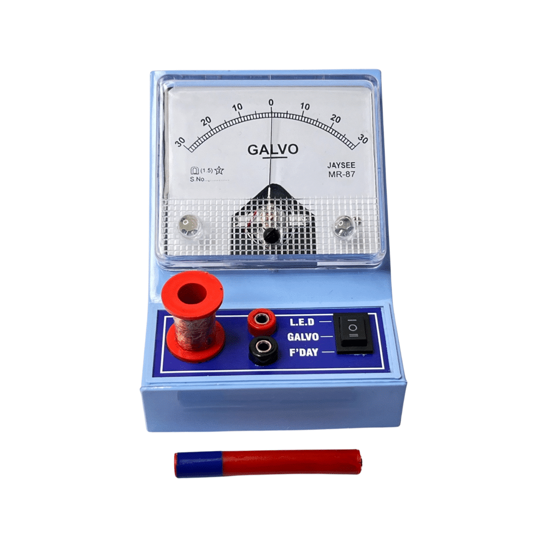
In electrical measurements, two essential instruments play a significant role: the ammeter and the voltmeter. Both instruments measure electrical quantities but serve distinct purposes and provide different information. This article explores the key differences between ammeters and voltmeters, shedding light on their functions, applications, and operation principles.
Table of Contents
1. Introduction
Electrical measurements are vital in various domains, such as engineering, physics, and electronics. Ammeters and voltmeters are two widely used instruments that enable accurate measurement of electrical quantities. Understanding their differences is crucial for using them effectively and interpreting the measurement results correctly.
2. Ammeter: Definition and Function
An ammeter is an instrument designed to measure electric current. It provides information about the amount of current flowing through a circuit. Ammeters are connected in series with the circuit under test, allowing the current to pass through them. They typically have a low resistance to minimize any influence on the measured circuit.
3. Voltmeter: Definition and Function
On the other hand, a voltmeter is used to measure the voltage across a component or between two points in an electrical circuit. It provides information about the potential difference present in the circuit. Voltmeters are connected in parallel with the circuit, allowing them to measure the voltage across the points of interest. They have a high resistance to ensure minimal current flow through the voltmeter itself.
4. Difference Between Ammeter and Voltmeter
4.1 Measurement Principle
Ammeters measure current by monitoring the flow of electric charge through a conductor. They utilize a shunt resistor or a current transformer to divert a known fraction of the current through the instrument, allowing the measurement of the current without significantly affecting the circuit.
Voltmeters, on the other hand, measure voltage by utilizing the principle of potential difference. They are connected in parallel with the circuit and measure the voltage drop across their internal resistance. By determining this voltage drop, the voltmeter can infer the voltage in the circuit.
4.2 Current and Voltage Range
Ammeters are designed to handle high current levels and are calibrated in amperes (A) or milliamperes (mA). They are commonly used in power distribution systems, electronic equipment, and electrical appliances.
Voltmeters, on the other hand, are used to measure relatively lower voltage levels and are calibrated in volts (V) or millivolts (mV). They are commonly employed in electronic circuits, power supplies, and testing laboratories.
4.3 Connection Method
Ammeters are connected in series with the circuit under test. They become part of the circuit and measure the current flowing through them. The current passes through the ammeter, allowing it to accurately measure the circuit’s current.
Voltmeters, in contrast, are connected in parallel with the circuit. They measure the voltage across the points of interest without interrupting the current flow. The voltmeter has a high input resistance, ensuring that most of the current continues through the measured circuit.
4.4 Internal Resistance
Ammeters have a low internal resistance, ideally approaching zero. This design allows them to draw only a minimal amount of current from the circuit under test, ensuring accurate, current measurement without significant disturbances.
Voltmeters, in contrast, have a high internal resistance. This high resistance prevents significant current flow through the voltmeter, ensuring the measurement does not alter the measured voltage.
4.5 Impact on the Measured Circuit
Ammeters directly impact the circuit being measured, as they become part of the circuit in series connection. Their low resistance can potentially cause a voltage drop or alter the current distribution in the circuit. Therefore, ammeters should be carefully selected and connected to minimize any interference.
Thanks to their high input resistance, voltmeters have a negligible impact on the circuit being measured. The current passing through the voltmeter is minimal, ensuring that the voltage measurement remains accurate and does not significantly affect the circuit’s behaviour.
5. Applications of Ammeters and Voltmeters
5.1 Ammeter Applications
Ammeters find extensive applications in various fields, including:
- Power distribution systems
- Electric vehicle charging stations
- Electrical appliances and machinery
- Circuit testing and troubleshooting
- Battery monitoring
5.2 Voltmeter Applications
Voltmeters are widely used in diverse applications, such as:
- Electronics and electrical circuitry
- Power supply testing and regulation
- Electrical safety inspections
- Calibration and instrumentation
- Renewable energy systems
6. Conclusion
In summary, ammeters and voltmeters are indispensable tools for measuring electrical quantities. Ammeters focus on measuring current, while voltmeters are designed to measure voltage. They differ in measurement principles, connection methods, internal resistances, and impact on the measured circuit. Understanding these differences is essential for selecting the appropriate instrument and ensuring accurate measurements. Finally, we have understood the difference between Ammeter and Voltmeter
7. Frequently Asked Questions (FAQs)
Can an ammeter be used to measure voltage?
No, an ammeter is specifically designed for measuring current and cannot accurately measure voltage.
Can a voltmeter be used to measure current?
No, a voltmeter is designed to measure voltage and cannot accurately measure current.
What precautions should be taken when using ammeters and voltmeters?
A: It is crucial to select the appropriate instrument for the measurement task, ensure correct connections, and consider the impact on the circuit under test.
Why is a voltmeter connected in parallel?
Voltmeters are connected in parallel because they measure the voltage across a component or between two points in an electrical circuit. Connecting them in parallel allows the voltmeter to directly measure the potential difference without interrupting the current flow through the circuit. By connecting in parallel, the voltmeter can provide an accurate measurement of the voltage without affecting the circuit’s behaviour significantly.
What happens if a voltmeter is connected in series?
If a voltmeter is connected in series with the circuit, it would interfere with the current flow and change the circuit’s behaviour. The voltmeter has a high resistance, and connecting it in series would impede the current flow, leading to incorrect voltage measurements and potential damage to the voltmeter.


